Ways to Program a Run Status for the VFD on an HVAC System

The entire team here at AirReps, which now includes the Control Products Group division, is dedicated to helping customers and partners with all of their HVAC needs, 24/7. That’s why when we had a customer reach out with an issue on their HVAC system with the VFD, we thought it might be pertinent to not only assist him with his issue, but also, to create a blog post that others could look to in order to rectify issues with their HVAC system as well.  

The question that has prompted our blog post today is fairly simple, but incredibly important when it comes to ensuring that your VFD is running properly. 

“Is there ever a time where the VFD status can say the pump is on, but the pump actually isn’t running? Whether from a burnt-out motor or any other reason. Will the VFD always recognize that the pump has failed?”  

This truly is a great question, and the answer contains imperative information for anyone with a VFD as an integral part of their HVAC system.  

To truly answer this question, we must go back to before the VFD even existed. Back in the old days, long before VFDs, customers would sometimes rely on Current Sensing Relays, often referred to as CSRs, in order to verify that amps were actually flowing through the motor wires. The CSR status gave us an indication that the motor was pulling amps and likely rotating, and to this day, many savvy users still add these CSRs to VFDs to show status.  

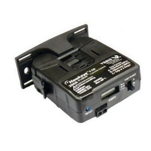
However, while in many cases helpful, these CSRs do need some adjustment. To ensure proper operation, you want them to go high when the motor is pulling a real load, and not necessarily show a run status in the event that the motor throws the belt or is otherwise operating under no-load conditions. The little screw pots inside the device can be finnicky, and they come in different sizes depending on amps that you need to read. 

Which leads to the question, can we just use the VFD programmable relay outputs to tell us the same thing? The answer is MAYBE, but there are several options that depend on your specific sequence.  

Below is a summary of the options, however, there are many, and I’m sure as soon as this article has been published, I will likely think of more options!  

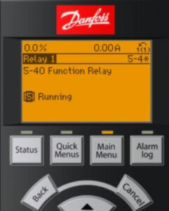
Option 1: This option to check the VFD on an HVAC system is typically default from the factory. Set one of the relay outputs 5-40 to “[5] Running”.   This tells you that the drive has a start signal and is trying to run the motor.  

Advantage:  This is easy and it’s the default setting on most drives. This application is very user friendly, as it’s easy for many to understand, and best of all, it usually works. If a motor phase was lost or if the system had experienced a ground fault the VFD, the system would trip, and the status would drop. 

Disadvantage: In this application, there is no guarantee that any motor is connected, just that we are asking the VFD to run and it thinks it is running.  That is, if the motor throws the belts or is physically disconnected, you wouldn’t necessarily know. 

Option 2: Set relay output 5-40 to “[6] Running/no warning”.  This version is a slightly more advanced variety of option 1, as it just adds the information that we don’t currently have any VFD warnings, such as high temp or current warnings.  

Option 3: Set relay output 5-40 to “[8] run on reference/no warning”.  Even more information here, now the VFD has reached the commanded speed with no warnings.  If the speed is within 5% of the setpoint then the relay goes high. 

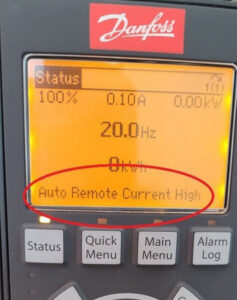
Option 4: Set relay output 5-40 to “[14] above current, high”.  Then adjust 4-51 to a current value that is slightly below the current at minimum speed.  

Advantages: This is now an electronic version of the current sensing relay, the VFD relay will only show a status when the current goes above the typical draw that you see above the motor minimum speed.  The motor is probably working and turning a load here. 

Disadvantages: The display will read “current high,” which might put some owners on high alert if done unexpectedly.  It doesn’t actually show as a warning, rather a message on the bottom of the display.  

Option 5: Utilize options one, two, or three, and in addition to those functions, add programing the “broken belt detection” sequence that is built into the VFD.  This will give you a “broken belt” warning, or trip if the amps are below a preset limit when the drive is running. 

Option 6: If you have completed any of the above options and read the actual motor current value over BACnet, then it will show up as AV5 and reads in amps. If the motor has amps and there are no other alarms reading, that is probably the best that can be done to see if the motor is doing work here. 

An important note to consider – on VFDs with bypass, if you are running in bypass due to a (hopefully) very rare failure in the VFD – how do we get the motor status? Since this is a rare and temporary emergency operating condition, you may not necessarily need a motor status here. If you manually switched it into that condition, and it is running full speed – if you really need a motor status here at the EMCS – you will probably need a CSR to tell you if the motor is spinning.  

As always, this blog post is meant to be helpful in operating your HVAC system, but this guide is not the end all be all in addressing issues with accessing your VFD. If you’re still having issues, or you’re not quite sure if your system is running properly, give our team a call. Whether you need a quick fix or it’s time to upgrade your entire system, someone on our team here at AirReps can assist!  

DAIKIN Rebel Heat Pump

How to Handle 100% Outside Air Without Fossil Fuels Even at -10 °F 

Designing HVAC systems for 100% outside air in cold climates has always been a challenge. When ambient temperatures drop below freezing, most DOAS heat pumps lock out around 20 to 25 °F. Without heat recovery or gas backup, the system can no longer provide heat, leaving building operators with limited and often costly options. 

For applications like laboratories, paint booths, or hospital isolation rooms where energy recovery is not allowed due to contaminated exhaust air, this issue becomes even more critical. Historically, these spaces have relied on oversized electric resistance heat or fossil fuels to keep systems operational during winter. 

The Electric Preheat Solution 

Daikin Rebel DOAS Heat Pump now has a proven way to operate in extreme winter conditions without gas or energy recovery. The Electric Preheat Kit is a bolt-on, field-installed accessory that tempers incoming outside air to protect the coil during defrost cycles. By maintaining the right entering air temperature, the system can operate in ambient conditions as low as -10 °F. 


How It Works 

  • The preheat kit raises the entering air temperature upstream of the coil to prevent freeze-up. 
  • The Rebel unit continues operating in full heat pump mode, even in sub-zero conditions. 
  • This eliminates the need for fossil fuels and supports electrification goals. 

Key Features 

  • Independent power feed with seamless integration to the MicroTech 4 controller 
  • Complete installation package with all necessary hardware and programming instructions 
  • Flexible kW sizing and cabinet configurations for a wide range of applications 
  • Cold climate design to prevent coil freeze during defrost cycles 

Where This Solution Makes Sense 

This technology is ideal for buildings that must exhaust 100% of their air and cannot use energy recovery due to health, safety, or regulatory reasons. 

  • Laboratories with fume hoods 
  • Industrial facilities using hazardous materials 
  • Healthcare isolation rooms 
  • Paint booths and finishing shops 

These facilities are common in Washington and fall under state exemptions from energy recovery requirements. 

Why It Matters 

As building codes and sustainability goals continue to move away from fossil fuels, many owners and design teams are looking for reliable ways to heat 100% outside air. The Electric Preheat Kit: 

  • Extends Rebel DOAS operation down to -10 °F ambient 
  • Reduces reliance on large electric reheat banks 
  • Ensures code compliance for exempt applications 
  • Supports decarbonization and energy efficiency targets 
  • Simplifies system design in challenging conditions 

A Practical Path Forward 

At AirReps, we help engineers and owners solve real design challenges. The Electric Preheat Kit for Rebel DOAS heat pumps provides a simple and effective way to keep 100% outside air systems running year-round in cold climates without fossil fuels. 

To learn more about how this solution can support your next project, contact your Account Executive or email [email protected]. 


Using the jog mode on Danfoss VFDs

Recently, we had an interesting inquiry from a customer about having a VFD go to a preset speed from a single input. In this case, that would pre-empt the speed the drive is being commanded to in normal circumstances.  

For example, when an exhaust fan ramps up typically by building pressure, while it really should go to full speed on a local command from a fire panel or other gas sensor.  

In the example above, the VFD is utilizing jog mode, which can also be used in cases where the system has a single input that you want to use to start the motor AND go to a preset speed, with no other speed reference required.  

What sets jog mode apart? This setting is different than other modes, such as fire mode, which simply ignores all alarms, and runs the VFD until it burns up. Sometimes, the sequence doesn’t need that, and so you can adjust to something a little simpler, such as jog mode. While jog mode still monitors the safeties and alarms from the VFD, plus, it will trip if limits are exceeded. 

Once the drive has been started and is running smoothly, typical s/s signal on term 12/18 and speed ref on 53/55, users can add the “jog” signal to terminal 29, when utilizing the example share in this blog post. However, on some new drives terminal 29 may be defaulted to “jog” already, so make sure to take a look at your system to find what your VFD requires specifically.  

Here are some additional steps to setting your VFD to jog mode:  

Set 3-11 “jog speed” to the speed you want the vfd to run 

Set 5-13 terminal 29 to [14] “jog” 

At that point, a contact closure between 12/29 will put the drive into jog mode and run at the jog speed.  

While we hope this is helpful, please feel free to reach out if you’re still stuck putting your VFD into jog mode, or if these steps didn’t work for your specific VFD system. Our AirReps team is always here and ready to help you with all things HVAC.  

BACnet and Digital Inputs for VFDs

If you’ve read our blog for a bit, you will have most likely realized that many of our topics come from the inquiries of customers and partners. Instead of helping just one customer at a time, we developed blog posts in order to share simple solutions to common HVAC issues.

Recently, a customer contacted us asking about an issue they were experiencing with their VFD. In their case, their VFD system would only start after a power cycle. Then, before running for some time, the VFD would ultimately stop once again – not good.   

In utilizing their system, they had been starting the drive with a contact closure on digital input 18, but also had the VFD connected over BACnet. 

In this case, where both communication and hardwired points are connected, it is possible to get multiple start or stop commands conflicting. This can result in unreliable start and stop behavior on a VFD system. This happens when the BACnet BV start point is placed on a graphic or in the schedule, while the BO is also scheduled or commanded. 

If you’re also experiencing this issue with your VFD system, here are some steps on how to remedy the situation and in order to have your VFD running smoothly once again.  

In cases where the VFD is only going to start using the hardwired point: 

Set parameter 8-01 “control site” to “[1] Digital Only”.  Now BACnet commands to start or stop the drive will have no effect, only the hardwire digital point will work. 

If this does not rectify the issues you are experiencing with your VFD, please feel to reach out to our team directly. Here at AirReps, we have a team of experts who are always ready to assist when it comes to all things HVAC.  

Danfoss Warning 34 Fieldbus Fault

Using your VFD should bring ease to your life, but we all know how difficult it can be when equipment is not functioning properly. Recently, we had an inquiry about Warning 34 on the Danfoss VFD, so we thought it would be the perfect topic for a blog post. Plus, we love a chance to make the customer experience easier while reassuring you with good news.  

And that good news is – while it may be stressful – Warning 34 on a Danfoss VFD won’t hurt anything in your overall system. While there are a few reasons why you might be greeted with this warning, in most cases, it will come up during the startup process, if the VFS has a communications option card, such as BACnet, but no communications are connected.  

After a couple of minutes without that communication, you will most likely see a “Fieldbus Fault W34,” or a communication failure on the card. While we understand this can be highly frustrating, it has no actual impact on the operation of the VFD unit. However, we understand that even with this in mind, you likely want the warning to go away as quickly as possible. So, we have put together a list of the top three steps you can take to reach a solution and get rid of the warning.

First, start with the simplest option. Connect to communication! Connect to the BACnet communication with some BACnet traffic.  

If that doesn’t help rectify the issue, power off the VFD and remove the card in order to restart the drive. This should prompt the VFD to show that there has been an “option change,” which should clear the alarm. This works well in cases where you do not and do not plan to use the card.  

If this option isn’t right for you, change function to 8-02, “control source,” from Option A to none. This way, the VFD won’t be looking for the control communications for the card, which means the warning will no longer come up on your VFD. 

The intention behind warning 34 is that if your VFD ever lost communications on the card, the system could trigger certain events. Events such as stop/full speed/pre-set speed, all things you might want your VFD to do if communications went down and control was lost. Having these measures in mind, plus ways to rectify them when they aren’t working as planned can help you to ensure that your VFD is running as smoothly and efficiently as possible. 

As always, if these steps don’t garnish the results you’re looking for, or if you’re having other issues with your VFD, please feel free to reach out to our team of HVAC experts here at AirReps today!  


HVAC Outside Airflow Measurements and COVID-19

Since the coronavirus first made headlines back in 2019, COVID-19 has been top of mind for citizens of the world around the globe. As counties and communities around the world have adjusted to this global pandemic, it has changed the way we live forever. The HVAC industry, like many other industries, has been greatly impacted by this moment in time. The impact of this moment in time will last far beyond the global pandemic, as it has shaped indoor and outdoor air requirements in a way that the industry will not return from.  

Of course, since the beginning of the COVID-19 Global Pandemic, our team has fielded many calls from customers and clients, especially those in the education industry. The world has changed, and many schools and universities are still trying to keep up and comply with new indoor air requirements mandated in order to bring students back, and to keep them safe while in school. 

First, we must cover some of the basic requirements, which can be found here on the official website for the United States Environmental Protection Agency, under the title, Healthy Indoor Environments in Schools During the COVID-19 Pandemic and Beyond. This page is not absolute in the requirements shared, but it gives a basis for understanding the changes schools and education facilities have faced since the start of the pandemic.  

The example brought to our attention by one of our customers was that as a result of the global pandemic, their team and organization had been running around with portable meters in an attempt to find an appropriate spot to read the measurements on the outside air.  

The difficulty is that spot measurements do not take into consideration varying conditions in all buildings, such as economizers, linkages, building pressure, occupancy changes, and heating vs. cooling, just to name a few.  

Instead, there are assets and tools that can be added to your existing HVAC system design to ensure that measurements are done consistently and accurately.  

This Ebtron Airflow Measurement Station stays in the ductwork for accurate and permanent monitoring, which makes it simple to get updates on your air quality. The Ebtron Transmitter has both analog outputs and optional data-logging, so you can verify continuously on the display or from your PC that you are meeting OSA requirements for your site. 

If your building needs a quicker fix, we suggest adding the Ebtron Airflow Measurement Station to the gyms, libraries, common spaces, and classrooms to provide stand-alone with data-logging to verify clean-air dilution. With this product, anyone can have the station quickly and it only requires 24vac power, making it a simple solution for all.  

For a longer-term update, connect the stand-alone Ebtron Airflow Measurements Stations to the BMS for continuous monitoring and alarming.    

Here at AirReps, we’re pros at redesigning and updating the HVAC systems in larger buildings, and we have plenty of experience with educational organizations. If you’re looking for more help, or if your building is ready for a new HVAC system design, reach out to our team today!  

Danfoss VFD Fire Mode

In the majority of our blog posts, we give tips, tricks, and guidelines that allow users to test them out on their own before having to go through the hassle of making a call in order to keep their HVAC system running smoothly. In this case, we give these tips with the express warning that before you try any of them out, you give our team, or your go-to HVAC experts a call.  

The Danfoss VFD has the ability to program an input a “fire mode,” meaning that the drive will ramp up and continue to run, regardless of any alarms.  

While some people like to refer to this as the “run until destruct mode,” and for good reason, today, we will be operating under the true name of “fire mode.”  

This setting is more frequently used for circumstances such as stairwell pressurization fans, where you don’t want too much pressure, as this would keep the stairwell doors from opening, but enough pressure to keep the fresh air flowing into the stairwell so that people can evacuate.  

In cases like this, you would want your VFD to ignore all of the internal alarms to keep the air flow going as long as possible in cases where it’s life or death.  

As you can imagine there are some risks to this. In many cases, the risk is that during routine testing of this feature, the VFD could be forced to exceed the programmed safeties and cause equipment damage, so please use caution here, and always consult with an HVAC expert!  The manufacturer can’t warranty a VFD that has been overloaded or damaged by fire mode testing.   

However, here we have some of the points that are useful when running these types of tests, or when setting your VFD up with this mode.  


24-09 Fire Mode Alarm Handling
 

Set this point to [2] “trip at all alarms-test” during setup and testing, this will keep you from damaging the VFD or motor during testing 

Change to [0] “trip and reset at critical alarms” ONLY when you are ready to arm the system for tenants 


5-11 Digital Input 19 (or pick any available input) 

Set to [37] “fire mode”, a contact closure on this input puts the vfd into fire mode 


24-00 Fire Mode Function
 

Set to [1] “Enabled” 


24-05 Fire Mode Preset Reference 

Set this to the value that you want the fan to run—usually the balancer will tell you this value based on pressure measurements from the stairwell 

You can also set a reference to come from an analog signal, call us to help set this up. 

As we mentioned above, this blog outlines a very important, but potentially damaging mode for a VFD. Please call us before testing or programming your VFD to ensure that your system isn’t poorly impacted. Our team of AirReps HVAC experts are always here to help!  

VFD sizing and NEC

When working with your VFD, the motor, of course, is a vital piece of the puzzle in making sure that your system is running smoothly. Often times, we have clients and partners ask us about VFD sizing in terms of the motors. 

In general, when it comes to the Danfoss VFDs, motors are sized to ensure that the VFD system has the ability to slightly exceed the max amp values, as show in the NEC Table 430-150. That NEC 430-150 table tells us a great deal of information, but the most important when it comes to motor sizing can be found in the excerpt below.  

  • The MAXIMUM amps that are allowed for a given HP motor (see 7.6amps for a 5hp/460v motor).  Most modern high-efficiency motors will be less than this max value by 10-30%. 
  • Low RPM motors may need MORE amps then specified on this table— the table is for standard 1800rpm motors.  If you remember your high school physics (heh!),  HP = Torque x RPM.  Since the RPM is lower, you need more torque to get the same HP.  To get more torque you need more amps from the VFD.  We see low RPM motors sometimes on direct-drive fans.  Verify the motor FLA on low rpm motors before ordering.  
  • Multi-motor applications may need to bump up one VFD size to accommodate the amps— To drive two 5hp/460v motors needs 7.6a + 7.6a = 15.2amps max.  If you look at the 10hp/460v value in the table, it is only 14amps max.  In this example we may need a 15hp VFD to run those two 5hp motors. 

In summary, while many in the industry frequently turn to this table for budgeting, it’s important to remember that users should also always utilize the Motor FLA from the data plate to ensure that the VFD is sized appropriately. It’s so important that it bears repeating, always use the Motor FLA to verify that the VFD is the correct size. It’s incredibly important in ensuring that your VFD system can run smoothly, effectively, and safely.  


As always, if you’re struggling to get the correct measurements or fit, or if you’re just not confident in your findings, reach out to our team for further assistance. Team AirReps is here for all of your HVAC system and HVAC design needs, and our experts are always ready to help!  

Viewing the status on Danfoss VFD inputs

Recently, our Control Products Group team had an inquiry from a customer who was asking how to view the status of the inputs on a Danfoss VFD, as they couldn’t quite figure out when the VFD system was on or off. While this may seem confusing at first, here at AirReps, we’re experts in HVAC, so of course we have advice on an easier way to check the status of your VFD system by utilizing the display.

First, head over to your HVAC system to your VFD and navigate to parameter 16-60, Digital Input. As a reminder, the display on the Danfoss VFD is binary, showing the status of all the inputs at that moment. Zero means the input is “off” and a one means that the input is “on”.

In order to decipher which digit corresponds to which input, we suggest you take a look at the chart below from the programming guide for the Danfoss VFD.

As a note, when utilizing this chart, input 18 is typically used for the start/stop. According to the chart, input 18 is “Bit 5”, and you count from the right starting with “Bit 0.” In summary, input 18 is going to be the sixth zero, for more help, see the picture below.

Here at AirReps, we know that these simple issues can cause major stress and frustration when not working properly. If you need any further assistance, please feel free to reach out to our team of experts today!

Ebtron Analog Output Scaling and Testing

Recently, a long-time customer and partner was inquiring about the analog output scaling for Ebtron transmitters. It’s a great question, as there is a plethora of information to understand when diving into Ebtron transmitters.

Below, we have listed some of the most important points for when users are just getting started with their Ebtron transmitters for analog output scaling and testing.

Probe based airflow stations come default as 0-5000 feet per minute (FPM) on the analog output 1 from the transmitter.  Note that this is a VELOCITY and not a VOLUME.

Fan inlet airflow stations come default as 0-10,000 FPM since they are generally a faster speed into the inlet cone.

For most systems, we recommend that you bring all of the transmitters velocity analog output (either 0-10v or 4-20ma based on the dipswitch) into your control system Analog Input (AI) as the same analog scaling— that is, regardless of duct size all of your Ebtron probe transmitters will have the same 0-5000FPM scaling into your AI.  We like bringing all of the transmitters in with the same scaling to avoid field confusion— at least initially.

Take each AI and multiply it by the duct area to get an AV showing the VOLUME in CFM.

VELOCITY x DUCT AREA = VOLUME FLOW

Having the volume flow be an AV allows you to do other operations on it later that you can’t do with an AI*.  We can look up the area from the packing slip if you don’t have it— call us if you need this value.
*Useful AV operations:  You can write a “0” to the AV on a windy rooftop when the unit is off, so there aren’t any weird airflows on the screen to distract the operators.

Here is an example using math to showcase how to best adjust the Ebtron transmitter’s analog output for scaling and testing.

If you brought the 0-10v signal in as 0-5000FPM on a 4’x4’ duct:

5000FPM x 16Ft^2 = 80,000CFM at max flow.  This means that 5V at the transmitter should show 40,000CFM on your EMCS display.

Based on how the manual describes it, we did the “manual conversion” to give more in-depth information.

USING THE TESTOUT BUILT INTO THE TRANSMITTER:

Ebtron gave us a great tool to help commission this by going into the setup/tools menu you can force the output to a certain %, and verify that we did all of the steps correctly.  If I command the output to 50%, I can measure 5v on the output and should see the EMCS display change to 40,000CFM in the above example.

As always, if you have any further questions, please feel free to reach out to our team! We’re happy to give you the hands-on assistance you need to ensure your system is running efficiently!