Since the coronavirus first made headlines back in 2019, COVID-19 has been top of mind for citizens of the world around the globe. As counties and communities around the world have adjusted to this global pandemic, it has changed the way we live forever. The HVAC industry, like many other industries, has been greatly impacted by this moment in time. The impact of this moment in time will last far beyond the global pandemic, as it has shaped indoor and outdoor air requirements in a way that the industry will not return from.
Of course, since the beginning of the COVID-19 Global Pandemic, our team has fielded many calls from customers and clients, especially those in the education industry. The world has changed, and many schools and universities are still trying to keep up and comply with new indoor air requirements mandated in order to bring students back, and to keep them safe while in school.
First, we must cover some of the basic requirements, which can be found here on the official website for the United States Environmental Protection Agency, under the title, Healthy Indoor Environments in Schools During the COVID-19 Pandemic and Beyond. This page is not absolute in the requirements shared, but it gives a basis for understanding the changes schools and education facilities have faced since the start of the pandemic.
The example brought to our attention by one of our customers was that as a result of the global pandemic, their team and organization had been running around with portable meters in an attempt to find an appropriate spot to read the measurements on the outside air.
The difficulty is that spot measurements do not take into consideration varying conditions in all buildings, such as economizers, linkages, building pressure, occupancy changes, and heating vs. cooling, just to name a few.
Instead, there are assets and tools that can be added to your existing HVAC system design to ensure that measurements are done consistently and accurately.
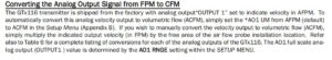
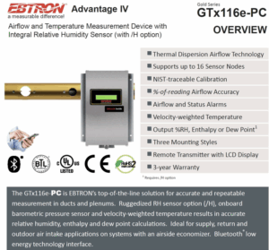
This Ebtron Airflow Measurement Station stays in the ductwork for accurate and permanent monitoring, which makes it simple to get updates on your air quality. The Ebtron Transmitter has both analog outputs and optional data-logging, so you can verify continuously on the display or from your PC that you are meeting OSA requirements for your site.
If your building needs a quicker fix, we suggest adding the Ebtron Airflow Measurement Station to the gyms, libraries, common spaces, and classrooms to provide stand-alone with data-logging to verify clean-air dilution. With this product, anyone can have the station quickly and it only requires 24vac power, making it a simple solution for all.
For a longer-term update, connect the stand-alone Ebtron Airflow Measurements Stations to the BMS for continuous monitoring and alarming.
Here at AirReps, we’re pros at redesigning and updating the HVAC systems in larger buildings, and we have plenty of experience with educational organizations. If you’re looking for more help, or if your building is ready for a new HVAC system design, reach out to our team today!